
BOOK 2 USER Manual
BOOK II Technical Reference & Maintenance Manual (The document is pending upload)
Schematic diagram(The document is pending upload)
![]() BOOK II MotherBoard Rev0.3.pdf
BOOK II MotherBoard Rev0.3.pdf
![]() BOOK II Upper motherboard Rev. 0.3.pdf
BOOK II Upper motherboard Rev. 0.3.pdf
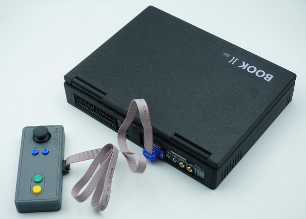
Size demonstration of floppy drive simulator
This is the schematic diagram of the RGB controller for BOOK2, which is currently unorganized and difficult to read. It will be replaced by annotated drawings. The RGB controller uses basic logic components to convert composite video signals into RGB signals one by one. (If you don't need to delve into the internal principles of RGB, please ignore it)
![]() BOOK2_RGB_SCH(Unorganized).pdf
BOOK2_RGB_SCH(Unorganized).pdf
The BOOK II contains approximately 120 DIP chips, making the soldering and assembly process excessively time-consuming. As a result, it is only produced in very limited quantities.
-----------------
Overview
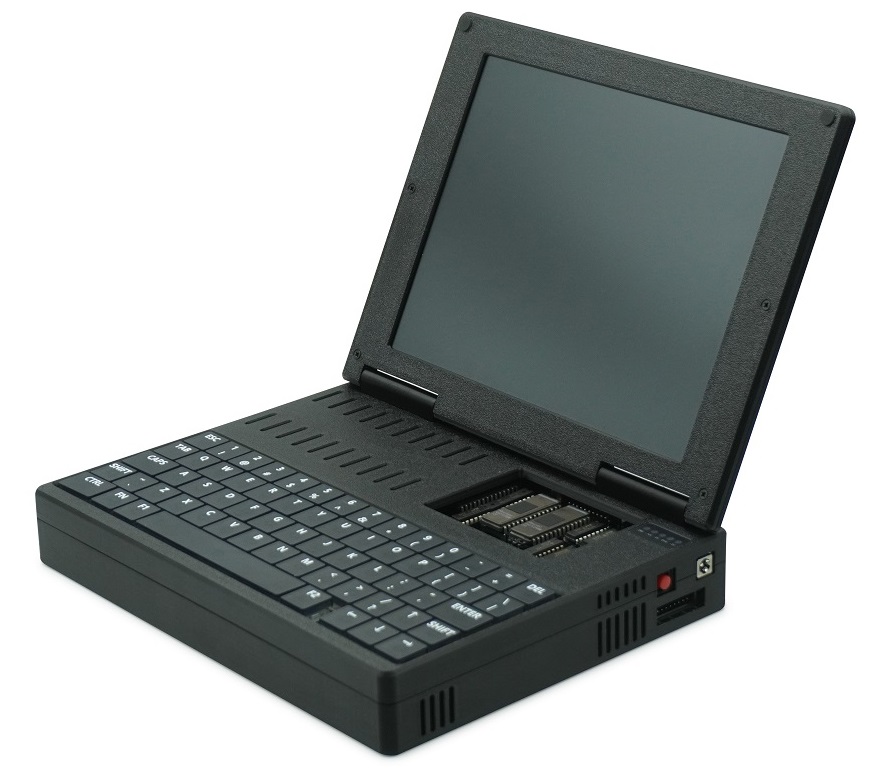
The BOOK II is a portable Apple II (Plus) compatible computer, redesigned using standard TTL chips and equipped with ROMs from early Apple II compatibles or clones. Beyond its core Apple II functionality, it integrates several built-in enhancements: an 80-column video card, a 16KB Language Card, a Z80 Softcard, a printer controller, and a Disk II compatible controller.
As a portable computer, the BOOK II features a built-in lithium battery, an RGB LCD, and a low-profile mechanical keyboard. It supports original Apple Disk II floppy drives as well as floppy drive emulators.
Features
CPU: 6502
SRAM: 48KB (+16KB)
Z80 Softcard
80 Column Video Card
16KB Language Card RAM
Disk II controller
Printer Interface
RGB Display
Mechanical keyboard/
Lithium battery (4x18650)
Expansion Bus Support (Slot 5)
=============================================================================

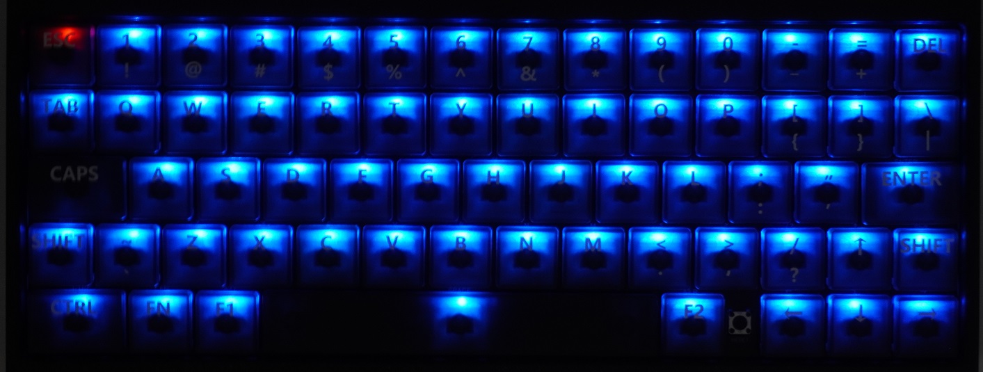
Low-profile mechanical keyboard with blue backlighting
The BOOK II’s keyboard features more keys than the Apple II, and its layout more closely resembles that of the Apple IIe.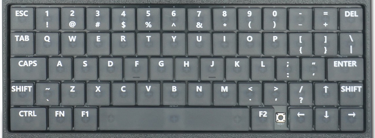
External interfaces:
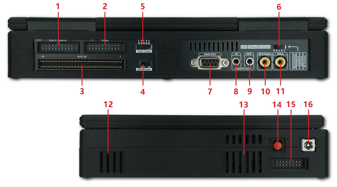
[1] 20Pin External DISK2 drive interface
[2] Printer Interface
[3] 50 pin system bus slot (Slot 5)
[4] Internal 80 column video card enable switch
[5] Text color selection switch
[6] RGB LCD control switch
[7] DB9 game control stick interface
[8] Cassette data in
[9] Cassette data out
[10] 80 column card video output
[11] Motherboard video output
[12] Speaker
[13] Cooling fan
[14] Power switch
[15] Game joystick interface
[16] Power adapter input (12V 3A)
[1] 20Pin External DISK2 drive interface
BOOK II supports the Apple Disk II floppy drive or compatible disk drive emulators.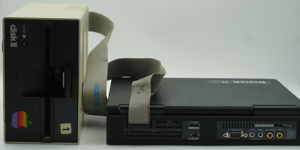
Reserved internal location for floppy drive emulator
An additional connector is reserved inside the unit. Users with the technical capability to design a disk drive emulator can construct one according to the reference dimensions and mount it using the pre-installed screws.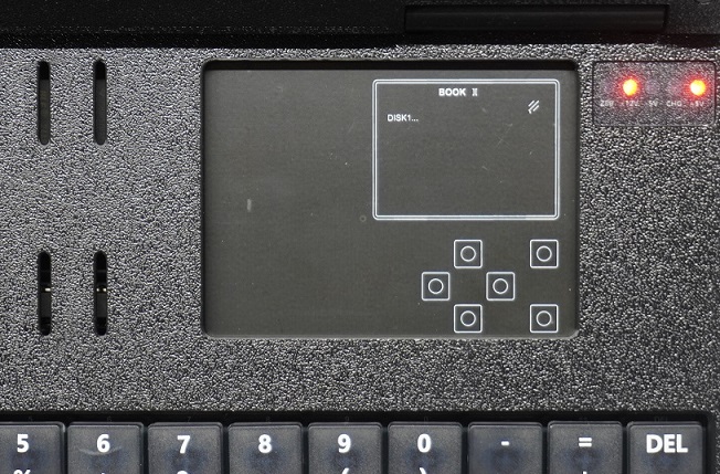
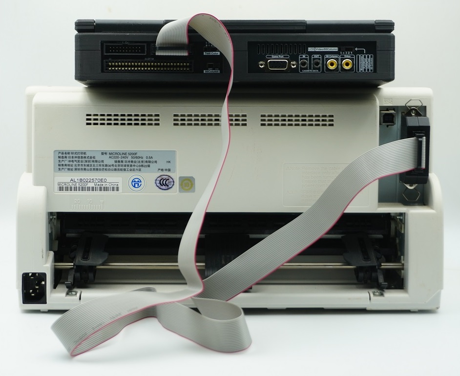
[2] Printer Interface
It can be connected to a printer via a 20‑pin ribbon cable with a CN36 header. (BOOK II has only been tested with the OKI 5200F printer)
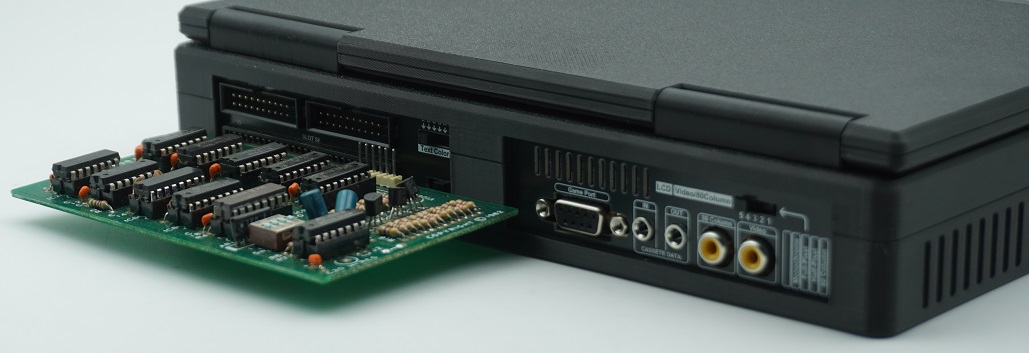
[3] 50 pin system bus slot (Slot 5)
The Apple II motherboard includes eight bus expansion slots for adding additional functionality. BOOK II directly integrates these common expansion cards. The corresponding slot numbers for the integrated cards are listed below:
SLOT0: 16KB language card memory
SLOT1: Printer Interface
SLOT2: (Not used)
SLOT3: 80Column Video card
SLOT4: Z80 Softcard
SLOT5: Used for external expansion cards
SLOT6: Disk II Controller
SLOT7: (Not used)
[4] Internal 80 column video card enable switch
The 80-column card enable switch is used to activate or deactivate the 80-column video card. This switch must be adjusted only when the unit is powered off.
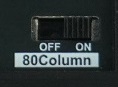
When the switch is set to OFF, the select signal for the 80-column card is disconnected from the SLOT3 connector, making the system behave as if the card is not present.
With the 80-column video card activated, you can enter 80-column video mode from the BASIC environment by typing PR#3. The LCD controller switch must also be set to position "1" (labeled 80 Column). If using an external video monitor, ensure it is connected to the 80-Column video port. Some software automatically detects the presence of the 80-column card on startup and switches to 80-column mode; in this case, you must also confirm the LCD controller switch is in position "1". To prevent software from automatically entering 80-column mode, set the 80-column card enable switch to OFF before powering on.
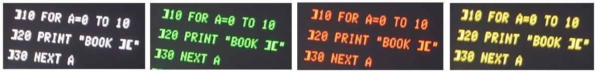
[5] Text color selection switch
This switch is used to select the color of on‑screen text. Except for graphic‑based characters, text in all display modes will be rendered in the selected color. The text color is modified within the RGB controller circuit, so this function does not affect an external video monitor. The BOOK II motherboard itself is not controlled by this switch.
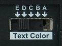
The following table lists the text colors corresponding to each switch position:
A-White B-Grey C-Green D- Orange E- Yellow
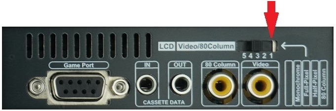
[6] RGB LCD control switch
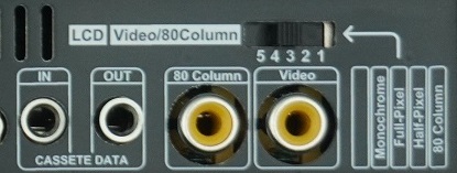
This switch selects whether the LCD receives video signal from the motherboard or from the 80‑column video card. When set to position "1", the LCD receives signal from the 80‑column video card. If no software is utilizing the 80‑column card at that time, the LCD will display no content. In positions "2", "3", "4", and "5", the LCD always displays signal from the motherboard; the difference between these positions is apparent only in Hires mode.
Position“2”(Half-Pixel):
This is a highly practical mode. When connected to a color monitor, the Apple II can display six colors in High‑Resolution (Hires) graphics mode. Based on the principles of NTSC color encoding, certain colors cannot appear in the same column, and each color pixel occupies two pixel units. As a result, graphics on a color monitor are not sharp, and text in graphics mode is often difficult to read. When connected to a monochrome display, the color‑stripped graphics become much sharper, which is ideal for productivity software. The BOOK II’s Half‑Pixel mode perfectly resolves the trade‑off between color and sharpness. It masks the excess pixels, delivering graphics identical to a monochrome display while preserving color
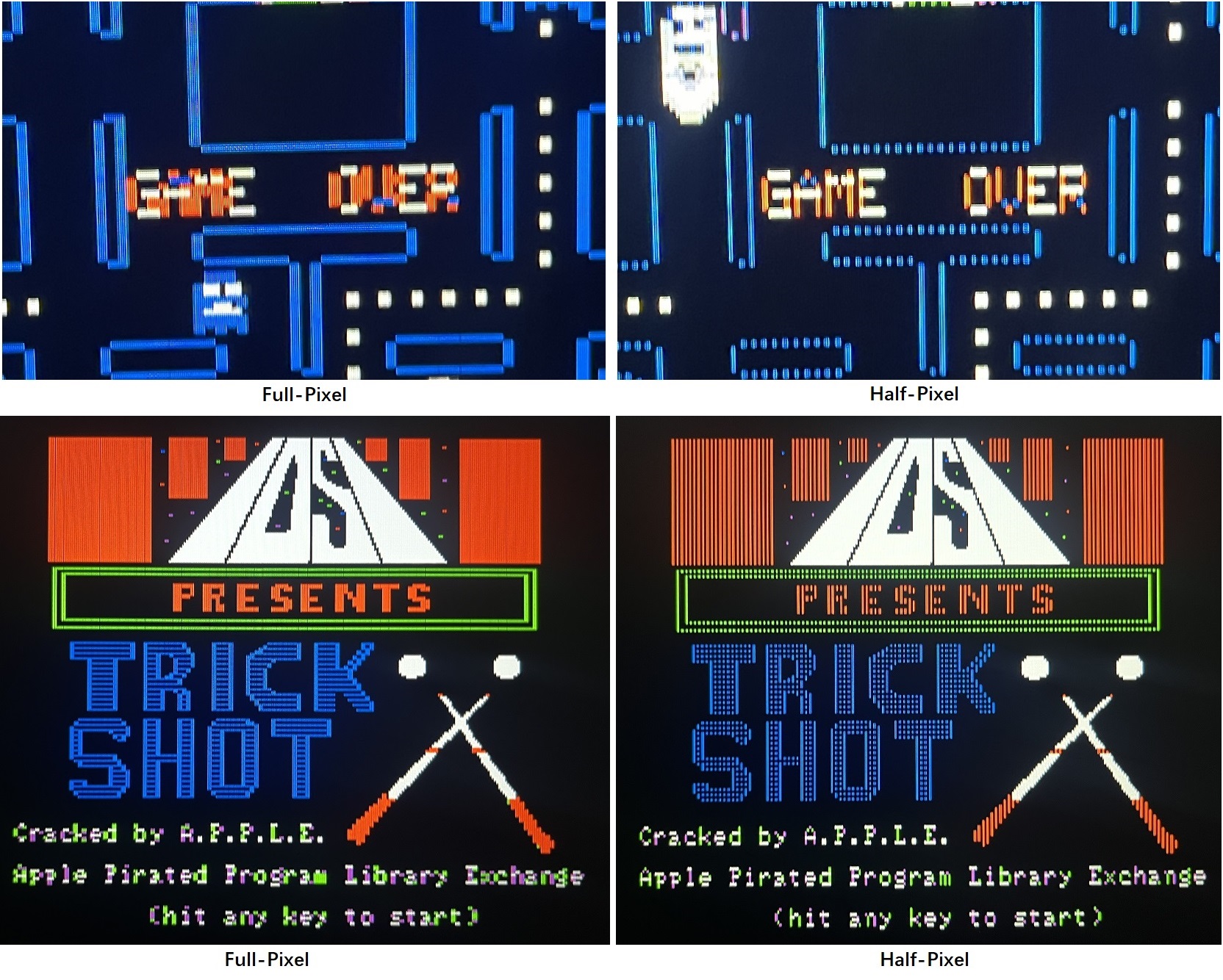
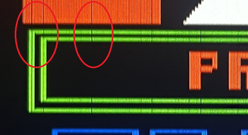
Position”3”(Full-Pixel):
In Full-Pixel mode, the Hires graphics will appear exactly as they do on a color monitor, with pixel blocks displayed consecutively column by column. Since RGB pixels are significantly sharper than composite video pixels, gaps may appear between adjacent pixel blocks.
Position”4”(Monochrome):
As the name suggests, in this mode, the color in graphics is filtered out, producing a display effect identical to that of an Apple II connected to a monochrome display. Additionally, the text color selector switch can be used to control the color of the graphics in this monochrome mode.

Position”5”(Reserved)
[7] DB9 game control stick interface
BOOK II’s game controller port is identical to that of the Apple IIe. It can be used with the A2‑JOY joystick, as well as any other controller compatible with the Apple IIe.
RGB display
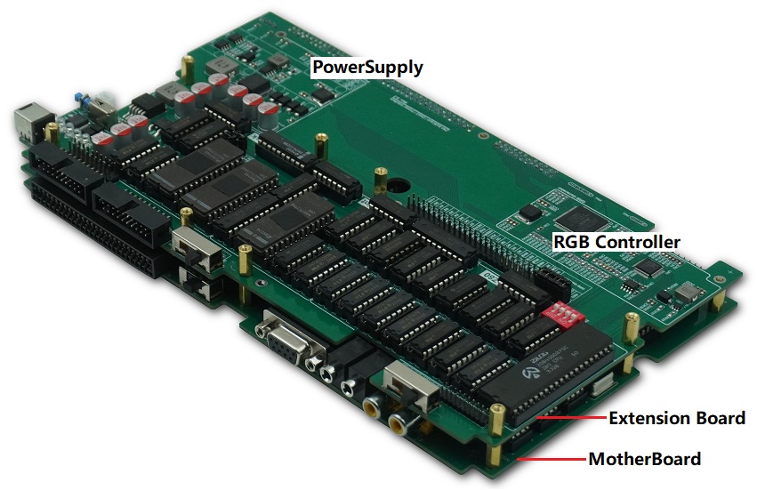
The RGB controller converts video data from the mainboard and the 80‑column card into an RGB signal. The entire process is implemented using pure digital logic, with no frame buffering or MCU computation involved. The image is not re‑sampled, so pixel positions on the LCD correspond exactly to the original television signal. A toggle switch on the rear panel selects whether the LCD displays video from the mainboard or the 80‑column card. The conversion logic is implemented as a schematic within a CPLD chip. The remaining logic gates in the CPLD are utilized to provide additional practical features, such as monochrome display and multiple text color options.
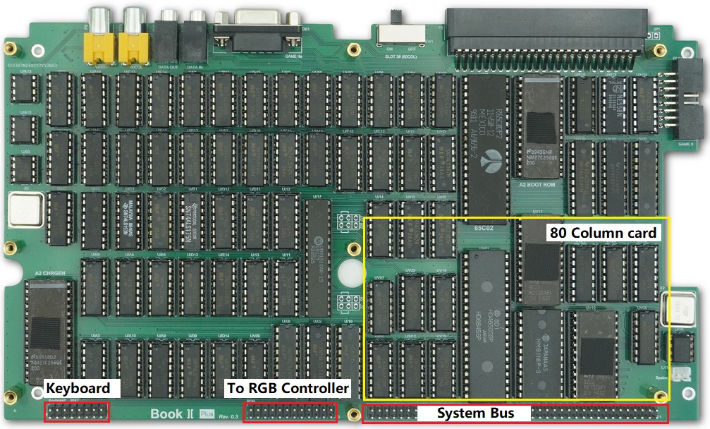
Motherboard
The motherboard is constructed using low‑power TTL chips.
 在线客服
在线客服